This article is written by valued CK Aero contributor Earl Haury
We often refer to incidence angles, CG location, and control travels with respect to our pattern airplanes, but just how accurate are the numbers? Does it even matter? We each may have different criteria for making these measurements. Sometimes it’s just for initial set-up to the designer’s specs, or maybe for future reference as we trim the airplane, or even to compare with what others have found to work.
A review of measurement criteria highlights the “buzz words” often used. Precision implies something good, but really means being able to make the same measurement with the same results, whether correct or not. Repeatability adds some definition in that it relates to the same person making the same measurement of something using the same tools. Results of a large number of measurements plotted will result in a bell curve that gives the variance to be expected. Reproducibility describes the variation of different persons making the same measurement. Note that the best results with these criteria say nothing about the accuracy of the measurement! Accuracy defines how close a measurement is to a known standard. All measurements are affected by these factors and great care, good techniques, and good equipment are necessary to minimize error.
Hmm – a precision judge can score an incorrect maneuver the same every time, but it takes accuracy to get the correct number! OK, I digress.
In measuring our airplanes we need to consider each factor, with accuracy being most important and precision a close second. If the data are just for our own references these switch, with precision taking the lead. Any comparison of measurements with those of others requires both sources to be accurate. In reality we generally accept the designer’s specs to be correct, get our airplane close, and make adjustments during the trim phase to achieve the desired performance. Some measure and record the final settings, others just fly what works. I do a little of both in that I’ll change things and observe results in flight. When I find something I like, I record those data so that I can accurately return to those settings if I stray off to something that doesn’t work as well. I also like to be able to discuss settings with others flying a similar airplane with confidence.
So what tools are necessary and where are there pitfalls to accuracy and precision? Simple may be best! The more sophisticated the tool the more opportunity for error to creep in. While it’s possible to make incidence or control travel measurements to less than 0.05° with a repeatability around ±0.02°, most can never appreciate that precision in flight. Generally, measuring to 0.1° ±0.05° is more than adequate.
Often our measurements begin with a level fuselage datum line which requires a good level. It’s important to note that all levels aren’t created equal! I don’t recommend the typical torpedo bubble level as they aren’t inherently precise, require a good eye to center the bubble, and usually aren’t adjustable. A machinist level is very good, usually accurate to 0.0005”/ foot, easy to read (bubble fits exactly between marks) and they’re adjustable. Digital levels may be best for our use. The popular Wixey (WR300T1) is economical, accuracy ±0.1°, has a zero button, and serves to set both incidence and control travels. Always check any level on a smooth surface by noting the reading, then rotating the thing 180°- the readings should be the same, adjust as necessary. Often the datum is the canopy flange, while the designer probably intended it to be, it may not be flat and different readings may be observed at different points. Average any irregularity by placing a 10” or so square piece of 1/16”+ aluminum sheet on the flanges with some pieces of bar stock to weight it over each flange. Place the level in the middle for the datum reference.
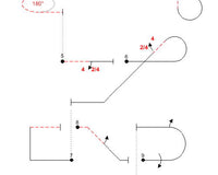
The first measurement of importance is wing incidence. Usually expressed in tenths of a degree positive, meaning the leading edge will be higher than the trailing edge with the datum level. A typical pattern airplane will generally be around +0.7°. With a wing chord of 18”, each 1/32” of incidence equals about 0.1°, or 7/32” for the desired 0.7°. While it’s cool to use the latest digital inclinometer, a simple height gauge is probably better for most. How simple? Some pencil marks on a piece of dowel simple. Just be sure to work from a flat surface, make sure the fuselage datum line is level with the dowel perpendicular, and marks to the dowel are made at wing LE – TE center lines. Anything marked to 1/64” is good to measure the difference between marks. Numerous Vernier or digital height gauges are available and are nice, but some are very pricey.
There are bar type model incidence meters available that have adjustable length bars with V-blocks to mate to the wing and either a mechanical or digital meter. One with a mechanical meter claims 1/8° (0.125° incidence for our 18” chord) accuracy for the meter and works OK. Using the Wixey digital level on the bar is an improvement in that the datum leveling step can be eliminated, making it a viable field measurement. Simply zero the meter on the datum and read the incidence from the V-block/bar. I really like the Aeroperfect digital meter (shown) as it’s accurate to 0.01° but, alas, is no longer available.
It can be difficult to get repeatable numbers with V- bars as there’s often error introduced in the pivot points, bar attachments, and bar flex. I made V-blocks without pivot points from aluminum stock. Fitted to an aluminum bar they work well for quick measurements with a digital meter. Any bar system must be checked for accuracy and precision if the numbers are to be believed! Do this by placing an 18” long straight metal bar with square ends in a vise (I use 3/16” x1”) and level it. Now install the incidence device / meter and note the reading – it should be zero to match the level reference bar. Do this several times to ensure repeatability. If you can’t get the same reading 10 times in a row – either figure out where the error is and fix it, or just trash the thing.
Everything that applies to wing incidence also applies to measuring stab incidence, except that most V-block / bar systems are too heavy to use on stabs. Here again, the simple height gauge can provide a reliable number. Lighter bars can be fabricated from 3/8” carbon fiber box with lite-ply V- block ends and work well with a digital meter. Again dismissing the need for a level airplane when making measurements.
With the incidence angles set and verified, the next parameter is the CG location. The designer will usually provide a range with a reference point (wing tube, canopy opening, etc.) Pattern planes will fly with CG placed over a pretty wide range, but will have a “sweet-spot” where everything seems to fall in place for a given wing incidence. The first job is to set the CG within the designers range and trim the airplane (using Bryan’s method) for best flight. Having found this point, it needs to be accurately measured and recorded. Why? Over the life of an airplane components are often changed and their weight varies. Props, spinners, motors, controllers, batteries, etc. With a known CG location, adjustments can be made quickly and the need to go through the process of re-finding the best CG avoided.
Again, sounds easy, but how is the CG of a pattern airplane measured with accuracy and precision? A couple of guys holding the thing by the wing tips and estimating the CG isn’t going to get it! If the canopy flange is strong enough (not many), then cutting a dowel to fit between the fuselage sides will allow lifting by the flanges and locating the CG by rolling the dowel until the airplane hangs level. Just as easy is to invert the airplane so that the canopy flange can be placed on a dowel, usually raised by blocks of wood for the airplane to clear the bench. Again the airplane is rolled back and forth on the dowel until level and the dowel location located. Then there’re the “CG machines” that support the airplane under the wings on some sort of pivoting plates. The airplane is moved until it balances. OK if the mounts don’t punch through the wing and often it’s hard to translate the balance point to a CG measurement. Also, it’s usually difficult for one person to manage these techniques.
I’ve had pretty good success with the Vanessa CG rig. Essentially the airplane is suspended by cords fore and aft of the wing under the fuselage by a central point. A plumb bob hanging from that point indicates the CG when the fuselage level is established by adjusting the cord lengths. (Search RCU “Vanessa” for details) This system isn’t without drawbacks. It isn’t really portable, lifting an unbalanced airplane requires care, establishing level with a free swinging system can be frustrating, even with calm air indoors the airplane and plumb bob seem to swing forever. Did I mention great concern about dropping the heavy plumb bob through a wing or fuse bottom? Also, error can be introduced by not ensuring the bob attachment point is perfectly central to the suspension point or the datum is not level.
The most promising is to weigh the pressure on each wheel and calculate the CG location from the center of the main gear bases, those weights, and the distance between the wheels. The fuselage must be level during measurements which means that when using a single scale, spacers are needed to keep it level while moving the scale from wheel to wheel. Various spreadsheets are available to help with the calculations.
Xicoy makes a system that solves some of these problems in that it uses a separate load cell under each wheel and has its own display system. All powered by 5-9v battery. Input the dimension between main and tailwheels, level the airplane, and it will output the CG location and where / how much weight to add / move to reach the desired CG. With the available inclinometers, one can be used to level the fuselage, so no need for a separate level. More Info on Xicoy Product
Even this device requires care in use to ensure accuracy. I find best practice is to turn it on and allow it to stabilize for 5 minutes. While this is in progress, measure the distance between the mains & tailwheel (or nose wheel). Use a taught string under the center of the mains and measure at the fuse centerline to the tailwheel. Likewise measure from the mains to the rear of the wing tube (a square from the bench to the tube is a good method) and calculate the desired CG location by adding / subtracting from that point. Enter these data into the device and save for future measurements. Place the cells alongside the wheels and tare the cells, then place them under the wheels. Lift the airplane by the struts (taildraggers) when placing the mains onto the cells to ensure there’s no side load imparted by strut flexing. Read the CG location from the display. This gizmo is fast becoming my favorite!
OK, that’s a bunch of info on measuring incidence and CG. These offer a variety of ways that can produce good results. What’s important is to achieve settings that trim the airplane for the best flight characteristics. While knowing just what those settings are isn’t terribly important, it’s good information to have.