The following is an article written by Jason Arnold, an Australian F3A pilot and big supporter of our trim methodology. He has had great success with Triangulation Trimming, and he’s not the only one. Many around the world have followed Bryan’s advice from a distance with remarkable results. We asked him to write about his experience because it’s one thing for us to tell you that we know what we’re talking about, but another thing altogether to hear from someone who has experienced the difference first hand. Jason also provides great insight into some of the difficulties you may experience along the way should you decide that you no longer want to accept “good enough” from your competitive pattern model.
Although I have never actually met Bryan Hebert in person, we have communicated via e-mail, RCU and Facebook for a number of years now. It’s fair and reasonable to say that with respect to trimming F3A models, there probably isn’t anyone better qualified or more importantly, experienced, to provide advice and guidance than Bryan. His ability to diagnose a trim problem without even seeing the model is simply amazing. That ability is nothing short of special and warrants great respect and appreciation.
"His ability to diagnose a trim problem without even seeing the model is simply amazing"
In this article I will describe how Bryan’s advice and trimming methods have been employed to transform a good flying model into a great flying model.
Some background information to start with.
"flying a model that has minor trim issues is like driving your car with badly worn tyres and then fitting new tyres and having a wheel alignment"
My name is Jason Arnold and I currently fly F3A (FAI) in Australia. For the last few years I have campaigned a Krill Spark Dynamic. Whilst this model has served me very well, there were always some minor issues that indicated things weren’t as perfect as they could be. Being a perfectionist, I just had to get to the bottom of it… The main issue of concern was the subjective maneuver spin entries. For some reason the Spark would nearly always spin to the left and the actual spin entry was a real lottery with regards to a nice stall i.e. nose drop and entry. Another issue was small rudder inputs after a radius or loop to maintain heading or the line. These small inputs were something that I was doing subconsciously and only added to pilot workload. To put this into some perspective, flying a model that has minor trim issues is like driving your car with badly worn tyres and then fitting new tyres and having a wheel alignment. Wow, what a difference!
Recently, Bryan Hebert released his Triangulation Trimming Guide to the modeling public. Before reading the guide, one should read the Triangulation Trimming article on this website. This will give you some background to the reasoning behind Bryan’s methods. If you haven’t purchased a copy of Bryan’s guide then I recommend you invest the $30 to get a copy. The guide gives you a starting point for setting up your model, a process to follow to obtain trim perfection and also a troubleshooting guide to point you in the right direction regarding adverse trim issues. The guide also dispels some long standing myths about trimming models. The aim of the game is to have as much as possible a “mix free” model and a model that fly’s the best it possibly can.
Whilst I have been following Bryan’s trimming methods for quite some time, only recently have we all had the opportunity to purchase his Triangulation Trimming Guide which goes into much more detail. Since purchasing Bryan’s guide, I have once again questioned things about the performance of my model and gained the motivation to continue the trimming process further. The other motivating factor was hitting the ceiling with my flight scores at competitions. Flying Pattern is all about continuous improvement and improving your scores is the ultimate goal. By following Bryan’s guide your model will fly better and as a byproduct, your scores should improve.
To be able to follow Bryan’s trimming guide you will need a few things:
- Patience – Take your time here and you will reap the rewards in flight. This means patience in the shed setting up the model and during the actual flight trimming.
- Honesty – This is of paramount importance. If you’re not honest with yourself or on what the model’s doing in the air Bryan’s guide will not work for you. If the model pulls or pushes in one or more flight tests then note it down for rectification.
- Tools – You need to have good tools for setting the model up accurately and the tools need to be repeatable. For many years I have used a Robart incidence meter. Whilst they are a good meter, they are inadequate for precision setting of the stab and wing incidence. I now use a Wixey angle meter (as suggested by Bryan) to do this task which will measure down to 0.1 degrees and once zeroed, is repeatable in its measurements. This is very important! One should also purchase a 36″ extension for your incidence meter. This will enable incidence settings / checks at the root of the wing. A good throw meter is also a prerequisite.
- Good weather – This is very obvious but recent experience trimming my Spark has proven that great weather (no wind) conditions are best for making very fine adjustments.
Another thing to do is read all you can about trimming. The RC Universe pattern forum is a great resource for information but one needs to be careful when deciphering the information. As with any forum, there are many self appointed experts but there are also real experts posting information. Bryan falls into the real expert category.
Back in March 2014, I started a thread on RCU about CK Aero’s new design the Allure. Being designed by Bryan Hebert it was only natural that he would chime in with pertinent information from time to time about the model and as it turns out, about trimming. One statement in particular made by Bryan caught my attention. At first I thought he had made an error but upon further investigation I have managed to learn something new and take Bryan’s trimming methods to the next level. The statement in question was “most, if not all composite models are twisted and require correction”. Prior to reading this statement, I was under the assumption that a molded airframe must be superior to a “built-up” structure in regards to straightness and consistency. This assumed that the mold was accurate and that airfoil shapes etc would be consistent. How wrong I was! When one really thinks about the manufacturing process there can be so many variables which can affect product accuracy and alignment. It’s up to the modeler to fix these variables and or inaccuracies.
"Most, if not all composite models are twisted and require correction"
First things first, a Wixey model 365 angle meter was ordered off eBay. This meter also displays the true angle as well as a relative angle which is perfect for setting up a pattern model.
The second item to be purchased was a 36” extension bar for my Robart Incidence meter. This allows incidence settings to be made at the wing root and also enables wing twist to be checked. Previously, I was only using the standard Robart bar which could only measure the incidence at 50% span on the wings.
So, what did I find out after purchasing my new tools?
"I managed to measure up to .5 degrees of twist!"
It turns out that Bryan’s statement is 100% right, the Sparks flying surfaces were in fact twisted. Those familiar with the Spark will know that both the wings and stabs have a stepped down leading edge which reduces the chord about 2/3rd of the way out towards the tips. The design concept here is to improve snap rolls. As it turns out, this step down section was where the twist in my flying surfaces was measured. I managed to measure up to 0.5 degrees of twist! All was not lost as the rectification process is quite simple but you need to take your time and be careful. The tool of choice was a hot air gun with an adjustable temperature facility. I used a Makita hot air gun which has very good temperature control. Basically, the twisted surface is heated up (top and bottom) and then twisted in the opposite direction to the existing twist and then allowed to cool. Be careful not to get the heat gun too close to the paint surface otherwise you may damage the finish! Again, be patient as you may have to repeat the process to get it spot on. After about two to three hours my surfaces were straight.
After the straightening process was completed, I then proceeded to reset / match the wing and stab incidences using the Wixey which is much more accurate and repeatable than the Robart although you still have to be careful. I’ll let you know why later in this article.
Another change that I made was to increase the control throws on both elevator and aileron for both spins and snaps. This required changing the servo arms to the Dubro variety which gave me a little extra length over the Futaba arms. This is where your throw meter comes into its own. I use a home-made throw meter which is based on a design concept seen on RCU a few years ago. It’s very light, accurate and repeatable. Importantly, it has virtually no friction at the pivot point. The one down side is that it’s not ideal for checking or setting throws at the field because wind can influence it. Again, take your time to set-up your throws so that you have equal aileron throws up and down on both wings and also repeat this with the elevators. To match the elevators I first set the throws on one side using my throw meter and then I set-up two straight sticks on each elevator with the sticks coming together behind the rudder. The sticks can be taped or clamped to the elevator surface. At this point I then adjust the other elevator throws and curve to match the other one. Interestingly, after straightening the stabs, my sticks were out by nearly 1/8”!
Onto the flying….
Flight 1
Now remember, this model has been in service for a few years so the basic incidence settings and CG have been left as they were for the initial flights. Bryan’s trimming guide goes into great detail about initial model set-up regarding incidence, thrust and CG settings etc.
Ok, into the air we go…. The first thing I did was perform numerous horizontal passes to get the elevator and aileron trim set for hands-off level flight. This task is fundamental to Bryan’s trimming methodology and must be repeated after EVERY adjustment to the model. This is where perfect trimming conditions make life much easier. Please be patient here even if all you do is multiple passes to ensure trim is correct. Once happy with the elevator and aileron trim, I performed a number of vertical up lines and down lines right on centre and noted down mentally what the model did. Then I performed a few knife edge passes with both left top rudder and right top rudder and again took mental notes of the models behavior. Right about now the battery was done so I landed and left the radio turned on to see what control surface trim was being carried.
Results:
Vertical up-line = Good.
Vertical down-line = Good (I do have a 5% down elevator mix at idle. My 5% = 0.4 degrees throw).
Left hand knife edge = A slight pull to the belly.
Right hand knife edge = A slight pull to the belly. Slightly more than in left hand knife edge flight
Trims – Aileron trim was good but a small amount of elevator down trim had been introduced.
Adjustments made:
Because the wing and stab twists had been corrected, Bryan suggested that reducing the incidence may be possible which would result in a happier model. As the up-line performance was good, I decided to reduce the incidence from 1.1 degrees to 0.6 degrees. This was done at the field with the Wixey. Note: Only one adjustment was made to the model.
Flight 2
Another battery was loaded and into the air we went again. First thing was resetting the elevator and aileron trim for straight and level flight. A few clicks of up elevator and some aileron trim were required which makes sense given the reduced wing incidence.
Results:
Vertical up-line = Pull to the canopy.
Vertical down-line = Pull to the belly
Left hand knife edge = A slight pull to the belly.
Right hand knife edge = A slight pull to the belly. Slightly more than in left hand knife edge flight.
Trims – A small amount of Aileron trim was introduced (about the thickness of a piece of paper) and elevator trim was now neutral.
Adjustments made:
The wing incidence was readjusted to 0.8 degrees to correct the pull to the canopy. Because a small amount of aileron trim was introduced, I paid special attention to matching the wing incidence with the Wixey. Now earlier in this article I said you had to be careful with the Wixey measurements. Because it’s a digital meter, you can have a situation where the meter flicks between two readings i.e. 0.0 degrees and 0.1 degrees. You therefore need to take great care in matching the two wings and stabs as a 0.1 degree difference can definitely be felt in the air.
Flight 3
Gee, I’m going through some batteries here…. All par for the course with trimming an electric model. Once again the first thing to be done was resetting the elevator and aileron trim for straight and level flight. A click or two of down elevator and one click of aileron trim were needed. Because the weather on the day was so nice these small adjustments translated into easily seen results in the air.
Results:
Vertical up-line = Good
Vertical down-line = Slight pull to the belly (The down line mix was adjusted in flight)
Left hand knife edge = A slight pull to the belly.
Right hand knife edge = A slight pull to the belly. Slightly more than in left hand knife edge flight.
Trims – Aileron trim was bang on neutral and elevator trim a whisker down.
Adjustments made:
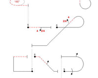
My radio has the facility to assign parameters to two separate digi adjusters for in flight tuning and adjustment. In this instance, my down line mix percentage was assigned to one digi adjuster. During flight three I was able to make a small adjustment to this down line mix reducing it from 5% (0.4 degrees throw) to 3% (0.24 degrees throw) for a dead straight down line.
For the next flight we will move the flight batteries forward by 1/4″. This will effectively move the CG slightly forward which should help with the knife edge pull to the belly (this is straight from Bryan’s guide). Many F3A pilots will simply add a rudder to elevator mix to correct this problem. Mixing knife edge problems out is common practice out there in the pattern community and believe it or not, is actually hiding an issue. Read on and you’ll see why this is the case.
Flight 4
The only change made for this flight was moving the flight pack forward by 1/4″. I rechecked the model for straight and level flight which resulted in one click of up elevator trim for hands-off level flight.
Results:
Vertical up-line = Good.
Vertical down-line = Good.
Left hand knife edge = A slight pull to the canopy.
Right hand knife edge = A slight pull to the belly.
Trims – Elevator trim was now neutral.
Adjustments made:
We are now getting pretty close with the Spark trim. It’s time to look at why the knife edge flight has both a pull to the canopy and pull to the belly. A quick referral to Bryan’s trim guide reveals four possible causes in order of priority. The highest priority item was to check the incidence of both stab halves are matching. As it turns out, there was less than 0.1 degrees difference between the two stab halves. This gets down to taking extra care with the measurement (as per previously mentioned with wing incidence) to make sure the stab halves match perfectly. It took me a good ten to fifteen minutes to get this adjustment right but the end result was certainly worth that time investment. Because the stab incidence was slightly changed, the sticks were put back on the elevators to recheck the throw adjustment. A small adjustment was required to rematch the elevator throws.
Flight 5
The straight and level trims were checked again but no adjustment to trim settings was required. I then proceeded to recheck the knife edge performance and the difference could be seen “straight” (pun intended) away. Now both knife edges are as straight as a die with no mixing required. It’s truly amazing that such a small change could make such a difference. The change was so small that many people may overlook it!
Results:
Vertical up-line = Good.
Vertical down-line = Good.
Left hand knife edge = Good.
Right hand knife edge = Good.
45 degree up-line = Good.
45 degree down-line with idle = Good.
Trims – All are neutral.
Adjustments made:
No adjustments made at all.
Earlier in the article I mentioned that I’ve always had problems with spin entries. It’s pleasing to see that since straightening the flying surfaces and making the small adjustments mentioned above, the model now enters spins infinitely better than it did. The model will now drop the nose and just sit there waiting for me to tell it which way to spin. Absolutely awesome! The model has also greatly improved throughout the rest of the preliminary schedule and is certainly much less workload to fly and maintain a heading or line.
During this process I have learnt so much from Bryan’s advice and his Triangulation Trimming Guide. Some old assumptions have been proven wrong and the old adage of “near enough is good enough” has been totally dispelled. Do things as accurately as you possibly can and you’ll benefit greatly from the extra effort. As you have read, only very small changes were made to the model after each flight and in most cases, one small adjustment improves two or more trim issues. This is Triangulation Trimming at its best.
Has the trimming process ended? No, that’s very unlikely. The great thing about F3A is that you never stop learning and the trimming process never truly ends. It’s a great challenge!
Thank you for sharing your vast trimming knowledge and experience with me Bryan.